 +86 18531742341
Leave Your Message
Choosing the right Ringlock Scaffolding System in 2026 requires more than comparing prices or counting components. Global buyers need equipment that performs consistently on busy construction sites, where muddy ground, uneven loading, and repeated assembly can expose weak design choices. A dependable system should include precisely manufactured standards, ledgers, rosettes, base collars, adjustable jacks, platforms, and secure access components. Small details matter. A loose connection can affect an entire working bay.
This guide evaluates leading ringlock solutions through practical purchasing concerns, including load capacity, steel quality, corrosion protection, dimensional accuracy, transport efficiency, and supplier support. It also considers factory quality control, product testing, technical drawings, inspection records, and the availability of replacement parts. These documents help buyers compare suppliers with greater confidence. Regional requirements may differ, so every project team should verify local engineering rules and site conditions before ordering.
Real sites are rarely perfect.
A system may look excellent in photographs but perform differently after months outdoors. Galvanizing thickness may vary. Labels may be unclear. Delivery schedules can slip. These risks deserve honest attention. No comparison is completely universal, and the lowest quotation is not always the safest investment. By combining technical evidence with practical field experience, this overview helps contractors, distributors, and project managers identify a Ringlock Scaffolding System that balances safety, durability, efficiency, and long-term value.
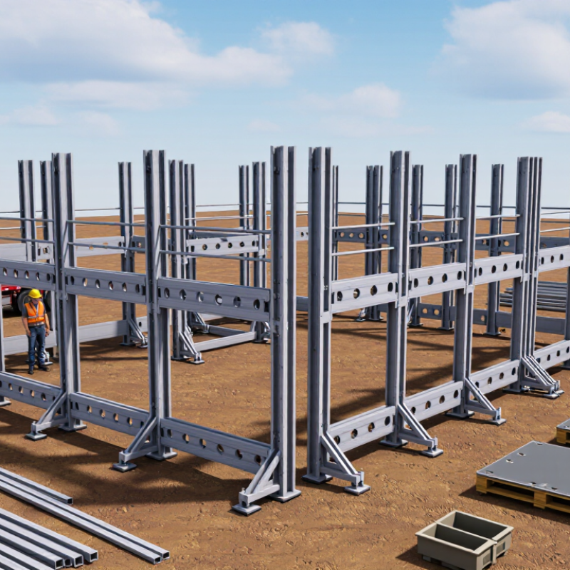
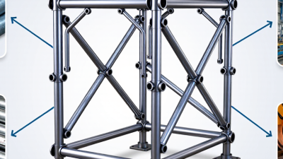
Ringlock scaffolding is built around four practical parts: standards, rosettes, ledgers, and wedge connections. Standards are vertical steel tubes that carry the main load. Each rosette is welded to a standard at 0.5 metre intervals, creating consistent connection levels. Ledgers lock into these rosettes and form the horizontal frame.
The 0.5 m node spacing gives crews more adjustment points than wider spacing systems. This helps when platforms must follow stairs, tanks, uneven floors, or changing elevations. On site, I check that ledgers sit fully inside the rosette cups before tightening the wedges. A firm hammer strike should secure the joint, but excessive force can damage components.
Small details matter. Standards need sound base plates, proper alignment, and stable foundations. Rosette welds should be visually checked for cracks, distortion, or incomplete bonding. Ledgers must match the intended bay length and remain free from severe bends. Do not assume a clean appearance proves structural reliability. I have seen well-painted components fail inspection because their dimensions were inconsistent. That mistake is easy to miss. Global buyers should request material certificates, dimensional records, load data, and independent quality inspections before shipment. Local regulations and an engineer’s design still control final use.
| Component or Buying Dimension | Typical Specification or Configuration | Function in the System | Important Technical Notes for Global Buyers |
|---|---|---|---|
| Ringlock Standard | Vertical steel tube fitted with rosettes at regular intervals, commonly 0.5 m apart. Typical scaffold tube outside diameter is 48.3 mm. | Transfers vertical loads and provides the main vertical connection points for ledgers, braces, and other system components. | Available lengths vary by supplier and project design. Confirm wall thickness, steel grade, welding quality, straightness, and allowable working load through test or design documentation. |
| Rosette | Round forged or welded node plate with eight connection openings: four narrow openings for right-angle connections and four wider openings for diagonal connections. | Creates a multi-directional, wedge-lock connection between the standard and horizontal or diagonal members. | The rosette is normally fixed to the standard at 0.5 m vertical increments. Actual hole geometry and plate thickness should be checked against the applicable system specification. |
| Ledger | Horizontal tube with welded end heads and captive wedges. Common bay lengths include approximately 0.73 m, 1.09 m, 1.40 m, 1.57 m, 2.07 m, 2.57 m, and 3.07 m, depending on the system. | Connects standards horizontally, maintains bay geometry, supports platforms when designed for that purpose, and helps resist lateral movement. | Ledger length must match the required bay width and loading arrangement. Do not treat every ledger as a platform bearer unless the design specifically permits it. |
| Diagonal Brace | Steel tube brace with compatible wedge heads, selected for the bay width and vertical lift arrangement. | Provides longitudinal and transverse stability and limits racking of the scaffold structure. | Brace layout depends on scaffold height, wind exposure, tie pattern, bay geometry, and the approved design. Bracing should not be omitted based only on low platform loading. |
| Base Collar or Starter | Short steel starter section installed between the adjustable base and the first standard, usually incorporating a rosette or connection point. | Creates the first usable node above the base and helps establish the initial lift height. | The first node elevation varies by system. Check clearance for base jacks, toe boards, access, and the required working platform level. |
| Adjustable Base Jack | Threaded steel spindle with a base plate and adjustable nut. Common adjustment ranges are approximately 300 mm to 600 mm, depending on the product. | Levels the scaffold on uneven supporting surfaces and transfers loads into sole boards or another suitable foundation. | Jack extension must remain within the manufacturer's or engineer's permitted limit. Use adequate sole boards and verify ground bearing capacity before erection. |
| U-Head Jack | Adjustable threaded spindle fitted with a U-shaped head, commonly used with beams, formwork, or temporary support arrangements. | Supports primary or secondary beams and allows height adjustment at the top of a temporary support structure. | A U-head support arrangement is not automatically equivalent to a full access scaffold. Confirm the intended use, load path, bracing, and engineering calculations. |
| Working Platform | Steel, aluminum, or timber-compatible scaffold deck selected for the bay width and intended duty load. | Provides the surface for workers, tools, and materials. | Platform width, clear access, slip resistance, securing method, and load class must be specified. Platform components should be compatible with the ledger and bearer arrangement. |
| Toe Board | Edge protection board or steel toe board installed along exposed platform edges. | Helps prevent tools, materials, and other objects from falling from the working platform. | Height and installation requirements vary by local regulation and project risk assessment. Toe boards do not replace guardrails or midrails. |
| Guardrail and Midrail | Horizontal edge-protection members connected to standards at suitable platform elevations. | Reduces the risk of workers falling from open platform edges. | Required rail heights, openings, and edge-protection details depend on the governing jurisdiction. Confirm requirements before shipment and erection. |
| Access Ladder or Stair Tower | Internal ladder bay, inclined stair unit, or dedicated stair tower compatible with the ringlock grid. | Provides safe access between working levels and supports material or personnel movement where permitted. | Access selection should consider traffic volume, evacuation needs, platform openings, handrails, landing dimensions, and local occupational safety rules. |
| Platform Lift and Node Spacing | Standard vertical node spacing is commonly 0.5 m, allowing platform levels to be arranged at practical increments. | Enables flexible lift heights and helps coordinate platforms, guardrails, braces, and access components. | A 0.5 m node interval does not by itself define safe platform spacing. The final lift arrangement must account for working height, clearance, loading, bracing, and site conditions. |
| Connection Type | Wedge-and-rosette connection assembled by inserting a ledger or brace head into the rosette and driving the captive wedge into position. | Creates a fast, multi-directional, largely captive connection with limited loose hardware. | Wedges must be fully seated and secured using the specified installation method. Damaged, distorted, or incompatible heads and rosettes should be removed from service. |
| Common Material Options | Structural steel components with hot-dip galvanized, electro-galvanized, painted, or untreated finishes. | Provides the required strength while allowing the buyer to select corrosion protection for the working environment. | Hot-dip galvanizing generally provides stronger long-term corrosion protection than paint or electro-galvanizing, but coating selection should reflect exposure, storage, handling, and repair requirements. |
| Typical Tube Reference | 48.3 mm outside diameter is widely used for ringlock scaffold tubes; wall thickness and steel grade vary by design and market. | Allows compatibility between standards, ledgers, braces, collars, jacks, and accessories when they are produced to the same system dimensions. | Outside diameter alone is not enough to verify compatibility or capacity. Request dimensional tolerances, steel grade, wall thickness, welding details, and component test records. |
| Design and Compliance Documents | Project-specific drawings, load calculations, assembly instructions, inspection records, and material or coating certificates. | Demonstrates that the scaffold has been selected, erected, inspected, and used for its intended purpose. | Common reference frameworks include EN 12810, EN 12811, AS/NZS 1576, and applicable national workplace-safety rules. The governing standard must be confirmed for the project location. |
| Load Capacity | Determined by the complete scaffold configuration rather than by a single component. Platform duty classes may range from light-duty to heavy-duty applications. | Defines the permitted combination of workers, tools, stored materials, platform self-weight, wind effects, and other applied loads. | Never use a generic load value without a design basis. Capacity depends on bay size, lift height, standards, ledgers, braces, ties, foundation, eccentricity, and environmental loads. |
| Inspection and Maintenance | Pre-use checks, periodic inspections, post-alteration inspections, cleaning, sorting, and controlled repair or replacement. | Helps identify bent tubes, cracked welds, damaged wedges, deformed rosettes, excessive corrosion, and missing components. | Components with structural damage should be quarantined. Repairs should follow an approved procedure and should not alter connection geometry or reduce the original design capacity. |
| Global Purchasing Checklist | Component schedule, bay and lift dimensions, quantity take-off, finish, packing method, documentation, inspection requirements, and delivery terms. | Reduces compatibility, quantity, customs, and installation risks for international projects. | Request samples or dimensional inspection before mass production when components from multiple sources will be combined. Confirm metric dimensions, applicable standards, packaging, and replacement-part availability. |